Cooling towers are usually classified in the following three ways:
- Fan type
- Air flow direction
- Water Circuit
In this blog we have tried to briefly cover these three sets of classifications, their applications and pros & cons of each type of Cooling Tower.

1. Classification – Fan Type:
1.1 Induced Draft: In these cooling towers, a fan located in the exiting air stream, draws air through the tower. Air is drawn in from the intake louvers at the bottom and is discharged through a fan at top
- Simple and easy to maintain design (with accessible motor)
- Lower energy consumption compared to forced draft cooling tower
EVAPCO’s induced draft series

AT/UT/USS EVAPCO Open Circuit Induced Draft Cooling Tower Brochure
AXS EVAPCO Open Circuit Induced Draft (Cross-flow) Cooling Tower Brochure
ATWB, eco-ATWB and ATWB-hybrid EVAPCO Closed Circuit Induced Draft Cooling Tower Brochure
ATC-E EVAPCO Induced Draft Condenser Brochure
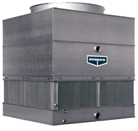
1.2 Forced Draft: In these cooling towers, the fan(s) (usually centrifugal) is usually located towards the basin of the cooling tower and forces the air stream into the cooling tower. The standard in low-profile, low-sound, centrifugal fan, forced-draft cooling towers, especially suited for indoor and ducted layouts or height-restricted areas.
- Low sound emissions as compared to induced draft
- Low profile (height) options available (EVAPCO LPT Series)
- Suitable for indoor/high static head applications
- Care required during operation, as small leaks can have troublesome effects due to forced draft’s pressurized upper casing
EVAPCO’s forced draft series

LPT /LSTE EVAPCO Open Circuit Forced Draft Cooling Tower Brochure
LSWE/LRWB EVAPCO Closed Circuit Forced Draft Cooling Tower Brochure
LSC-E and LRC EVAPCO Forced Draft Condensers Brochure
PMC-E EVAPCO Induced Draft Condenser Brochure

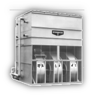

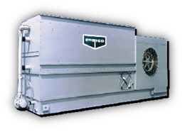
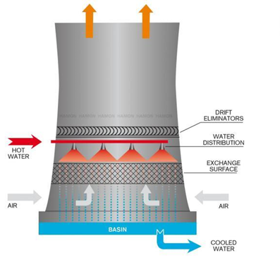
1.3 Natural Draft: These cooling towers do not use a fan. Natural air flow is produced by density differential b/w heated and cold air.
- Usually used in power sector
- Flowrates > 15500 LPS
2. Classification – Air Flow:
2.1 Counter Flow: Air moves vertically upward through the fill, counter to downward fall of water.
- Less footprint per cell than cross flow.
- Lower operating weight than cross-flow.
- Entire working system is guarded from sunrays, preventing algae growth hence good compliance with AS 3666.
- Coldest air is in intimate contact with the entire cross-section of water just before it falls into the basin.
EVAPCO’s Cross Flow series

Eco-air V Series Adiabatic, Eco Air V Series Dry, eco-Air Flat Series Dry Brochure
AT/UT/USS EVAPCO Open Circuit Induced Draft Cooling Tower Brochure
LPT /LSTE EVAPCO Open Circuit Forced Draft Cooling Tower Brochure
ATWB, eco-ATWB and ATWB-hybrid EVAPCO Closed Circuit Induced Draft Cooling Tower Brochure
LSWE/LRWB EVAPCO Closed Circuit Forced Draft Cooling Tower Brochure
ATC-E EVAPCO Induced Draft Condenser Brochure
PMC-E EVAPCO Induced Draft Condenser Brochure
LSC-E and LRC EVAPCO Forced Draft Condensers Brochure
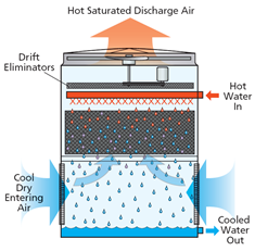

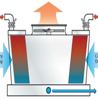
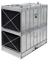
2.2 Cross Flow: Air flows horizontally through the fill across downward fall of water
- Lower operating cost as air flow is not directly opposing water flow (lower fan power)
- These cooling towers can be placed butted together next to each other as air intake is only from 2 out of 4 sides
- Capacities usually begin from 2MW, so not suitable for smaller applications
- Usually tough to comply with AS 3666
EVAPCO’s Cross Flow series

AXS EVAPCO Open Circuit Induced Draft (Cross-flow) Cooling Tower Brochure
3. Classification – Water Circuit:
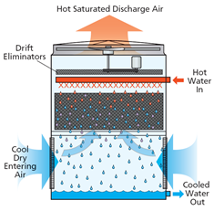
3.1 Open Circuit: All the water flowing through the cooling tower, comes in contact with the air and undergoes evaporative cooling. In applications where the equipment in the downstream of cooling tower is susceptible to fouling/scaling issues, a plate type heat-exchanger is introduced in between to limit the scaling/fouling of the heat exchanger plates and limit the scaling/fouling of downstream equipment like chillers.
EVAPCO’s Open Circuit series

AT/UT/USS EVAPCO Open Circuit Induced Draft Cooling Tower Brochure
AXS EVAPCO Open Circuit Induced Draft (Cross-flow) Cooling Tower Brochure
LPT /LSTE EVAPCO Open Circuit Forced Draft Cooling Tower Brochure

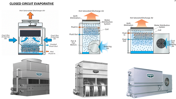
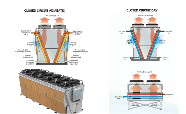
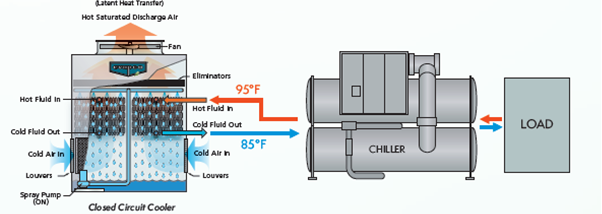
3.2 Closed Circuit: Primary water does not come in contact with air. Secondary water circuit may (evaporative or adiabatic) or may not (dry) be present.
EVAPCO’s Closed Circuit series

Eco-air V Series Adiabatic, Eco Air V Series Dry, eco-Air Flat Series Dry Brochure
LPT /LSTE EVAPCO Open Circuit Forced Draft Cooling Tower Brochure
ATWB, eco-ATWB and ATWB-hybrid EVAPCO Closed Circuit Induced Draft Cooling Tower Brochure
LSWE/LRWB EVAPCO Closed Circuit Forced Draft Cooling Tower Brochure
ATC-E EVAPCO Induced Draft Condenser Brochure
PMC-E EVAPCO Induced Draft Condenser Brochure
LSC-E and LRC EVAPCO Forced Draft Condensers Brochure
